Beckhoff CU8801-0000 Operations Instructions
Browse online or download Operations Instructions for Unknown Beckhoff CU8801-0000. Beckhoff CU8801-0000 Operating instructions User Manual
- Page / 33
- Table of contents
- TROUBLESHOOTING
- BOOKMARKS
- Table of contents 3
- 6 Troubleshooting 19 4
- 7 Assembly dimensions 20 4
- 8 Technical Data 29 4
- 9 Appendix 30 4
- 1 Foreword 5
- 1.3 Basic safety measures 7
- 1.4.1 National regulations 8
- 1.4.3 Operator requirements 8
- 2 Product Description 9
- 2.2 Appropriate Use 10
- 2.4 Interfaces 11
- 2.4.3 USB in (X 104) 12
- 2.4.5 Ground connection 12
- 2.4.6 Power Supply (X101) 12
- 3 Installation 14
- 4 Mounting 15
- CP29xx 16
- 4.2.2 Protective Earthing 18
- 4.2.1 Connecting cables 18
- 5 Operating Instructions 19
- 5.4 Emergency procedures 20
- 5.5 Shutting down 20
- 6 Troubleshooting 21
- 7 Assembly dimensions 22
- 8 Technical Data 31
- 9 Appendix 32
- 9.4 FCC Approval for Canada 33
Summary of Contents
Installation and Operating instructions for CP29xx Multi-touch built-in Control Panel with DVI/ USB Extended interface Version: 1.4 Date:
Product Description 2.2 Appropriate Use The multi-touch built-in Control Panel CP29xx is designed for industrial application in machine and plant e
Product Description 2.4 Interfaces X104 USB in X102, X103 USB out Ground X101 Power X106 DVI-E Input X105 USB-E Input 2.4.1 DVI-E Input (Digi
Product Description 2.4.2 USB-Extended Input (X 105) X105 Connection via standard-RJ45-cabel, not crossed The Control Panel is connected with the
Product Description 2.5 Connection Kits/ Connection Cables One 5-pole power supply connector is provided with the Control Panel. Optionally prefab
Installation 3 Installation 3.1 Transport and Unpacking The specified storage conditions must be observed (see chapter Technical Data). 3.1.1 Tran
Mounting 4 Mounting The Control Panel CP29xx is designed for mounting in control cabinets in machine and plant engineering applications. The ambien
Mounting 4.1.4 Mounting of the Control Panel The Control Panel is installed in the cabinet wall with clamping levers. For the cutout dimension of
Mounting 4.1.5 Fitting the power supply cable Fit the cables for the power supply of the Control Panel, using the included material for assembling
Mounting 4.2 Connecting the Control Panel Risk of explosion! Danger The Control Panel must never be connected or disconnected in an area that is
Operating Instructions 5 Operating Instructions 5.1 Switching the Control Panel on and off 5.1.1 Switching on The Control Panel does not have its
Operating Instructions 5.3 Servicing and maintenance 5.3.1 Cleaning Disconnect power supply DANGER Switch off the device and all connected devic
Troubleshooting 6 Troubleshooting Pixel errors Note Pixel errors in the TFT display are production-caused and represent no complaint-reason! Anom
Assembly dimensions 7 Assembly dimensions CP2907 with 7“ display, landscape (all dimensions are in mm) Notice mounting orientation Warning The ass
Assembly dimensions CP2915 with 15“ display, landscape (all dimensions are in mm) Notice mounting orientation Warning The assembly of the unit mu
Assembly dimensions CP2915 with 15“ display, portrait (all dimensions are in mm) Notice mounting orientation Warning The assembly of the unit mus
Assembly dimensions CP2916 with 15.6“ display, landscape (all dimensions are in mm) Notice mounting orientation Warning The assembly of the unit
Assembly dimensions CP2918 with 18.5“ display, landscape (all dimensions are in mm) Notice mounting orientation Warning The assembly of the unit
Assembly dimensions CP2918 with 18.5“ display, portrait (all dimensions are in mm) Notice mounting orientation Warning The assembly of the unit m
Assembly dimensions CP2919 with 19“ display, landscape (all dimensions are in mm) Notice mounting orientation Warning The assembly of the unit mu
Assembly dimensions CP2921 with 21.5“ display, landscape (all dimensions are in mm) Notice mounting orientation Warning The assembly of the unit
Table of contents Table of contents 1 Foreword 3 1.1 Notes on the Documentation 3 1.1.1 Liability Conditions 3 1.1.2 Trademarks 3 1.1.3 Pate
Assembly dimensions CP2924 with 24“ display, landscape (all dimensions are in mm) Notice mounting orientation Warning The assembly of the unit mu
Technical Data 8 Technical Data Risk of explosion! Danger Do not use the Control Panel in areas of explosive hazard! Pixel errors Note Pixel err
Appendix 9 Appendix 9.1 Beckhoff Support and Service Beckhoff and their partners around the world offer comprehensive support and service, making
Appendix CP29xx 31 9.2 Approvals for USA and Canada 9.3 FCC Approvals for the United States of America FCC: Federal Communications Commission Ra
Table of contents 4.1.4 Mounting of the Control Panel 14 4.1.5 Fitting the power supply cable 15 4.2 Connecting the Control Panel 16 4.2.1 C
Foreword 1 Foreword 1.1 Notes on the Documentation This description is only intended for the use of trained specialists in control and automation
Foreword 1.2 Description of safety symbols The following safety symbols are used in this operating manual. They are intended to alert the reader t
Foreword 1.3 Basic safety measures Before the Industrial PC is switched off, software that is running must be properly closed. Otherwise it is pos
Foreword 1.4 Operator’s obligation to exercise diligence The operator must ensure that • the product is only used as intended (see chapter Produc
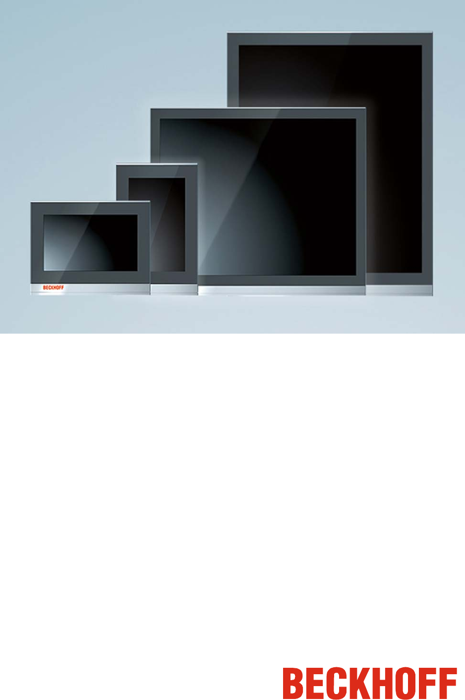
Product Description 2 Product Description 2.1 Product overview Front view of CP29xx The new Beckhoff panel generation with industry-standard multi
More documents for Unknown Beckhoff CU8801-0000

Related products and manuals for Unknown Beckhoff CU8801-0000
 (84 pages)
 (19 pages)
© 2020, manymanuals.com. All rights reserved. | 1.068 s |
 Manymanuals.com
 Manymanuals.de
 Manymanuals.fr
 Manymanuals.it
 Manymanuals.pl
 Manymanuals.cz
 Manymanuals.es
 Manymanuals-pt.com
Comments to this Manuals